GPIO on Raspberry Pi
GPIO stands for general purpose input output. It is so called low-level peripheral. RPi has 26 pins for multiple SPI, I2C and serial UART buses. In this section I will share some guides which can help you to start using this busses to use RPi to react with actual world :)
GPIO pins
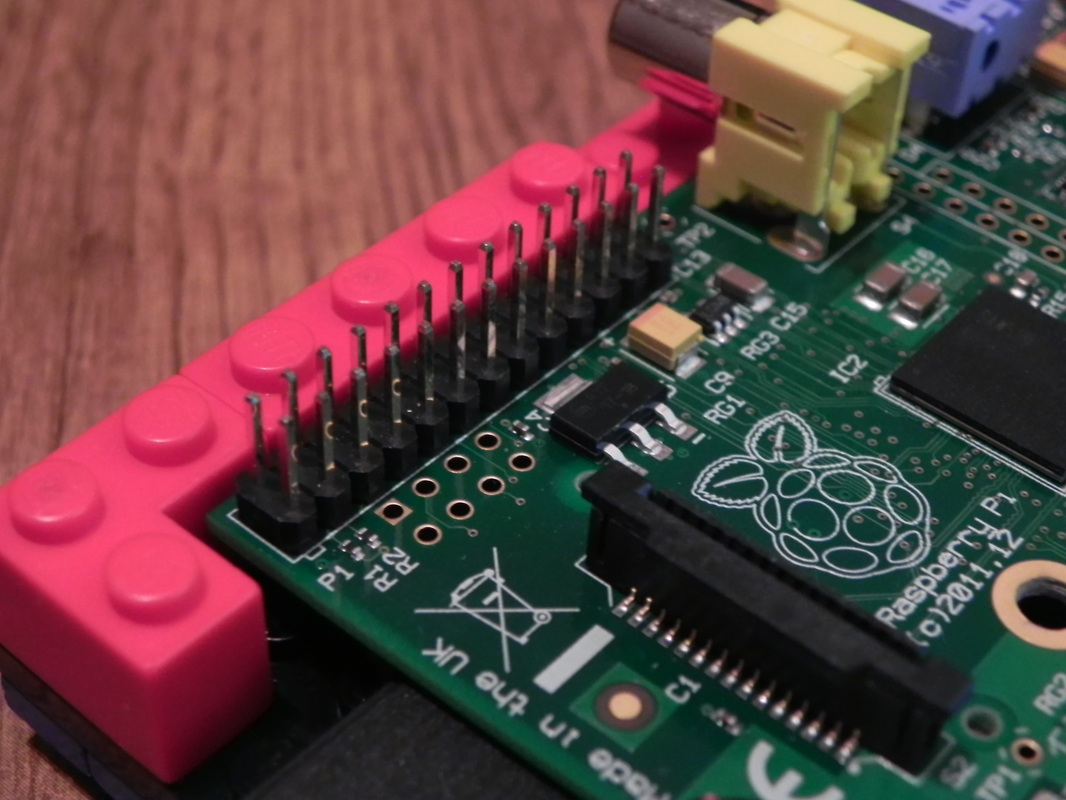
At first we have to find out which pin is pin 1. It is quite simple, you can see it on the picture above too (P1 - the closest pin to camera). Now here is picture with pinout where you can see which pin belongs to respective buses.
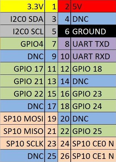
GPIO pinout
GPIO bus works only with 3,3V. Because RPi was primarly designed to be as cheap as it can be, there are no fuses or anything that would take care of your RPi in case of miswiring or something like that.